Quotes

Life is short, break the rules. Forgive quickly, kiss slowly. Love truly, laugh uncontrollably and never regret anything that makes you smile. - Samuel Longhorne Clemens (Mark Twain)

Friday, August 30, 2024

Modeling a Model Railroad - Adding Some Color

I probably doubled the number of buildings for the model. That involves cutting out a lot of little tiny slips of paper and then gluing them to the PVC sheets, its a bit tedious. Everything was starting to look pretty black and white so I figured it was time for some color.

I pulled out the Golden acrylics and went to work. It didn't take long using mixtures of three colors to get some variation between the buildings and that simple task was finished.
This is how it starts. Lots of little slips of paper.

Three Golden Acrylic paints and a filbert brush and this is what I ended up with.


Thursday, August 29, 2024

Modeling a Model Railroad - Double Diagonals

I realize that we are constantly fighting parallel lines on these narrow shelf layouts. Since I'm going to use cassettes on either end of the layout I need the mainline, at the very least, to exit off the end at 90 degrees. That requirement pretty much keeps the tracks parallel to the edge.

The other day when I was messing around with the diagonal road or viaduct on the right side it occurred to me that maybe two parallel diagonals would be better. This thought, of course, changed the direction of what I wanted to do next but since the whole purpose of this exercise is to try new things I opted to try a double diagonals. Of course this entailed suddenly building a whole lot of buildings with angled walls.

Here is the result (I'm using the other buildings to build up a background):

Elevated view of the tracks

A slightly lower view

From the left end looking towards the viaduct

Looking down towards the open end

Adding a view freight cars, today we are using the CF7 as motive power today


Tuesday, August 27, 2024

Modeling a Model Railroad - A Diagonal Road

Coming back around to viaduct discussion. It was suggested that perhaps just a diagonal road instead of a viaduct would be a better choice. It certainly removes any concerns about uncoupling freight cars in and around the viaduct.

I thought this through a bit and decided that instead of the two roads meeting at 90 degrees on the right side of the layout would be more interesting meeting at an angle. I made a road "template" and picked an arbitrary position and drew some lines. Looked interesting so I dug into it a bit more and made up some buildings that matched the angle to see how things might come together. How the diagonal road looks:

A broad overview of the layout. Still working on more buildings. Maybe both roads should be on a diagonal. I'll need to dwell on that thought a bit.


Since I still have viaducts on my mind and I have one that is long enough, let's replace that diagonal road with a diagonal viaduct:

In this configuration I think the viaduct is big enough to be recognized as a major road way. When the viaducts were first built in Denver they were used to get across both the Union Station tracks and the South Platte. They evolved from foot and wagon traffic, to street car and automobiles. I think its a viable option at this length.

I think with some taller buildings surrounding it, especially on the back edge, the viaduct could really be a scene on its own. The question becomes is it worth the difficulty it would add to switching the right side.

I didn't think this model would eat up so much time in the beginning but I enjoyed the exercise so far. I haven't even managed to think to much about the center and left sides yet, so there is plenty to come.

Monday, August 26, 2024

Modeling a Model Railroad - Viaducts, three choices

I'm a bit torn at this point. I want to include a viaduct because it will be good practice for the one that will be on the Wynkoop Street layout. However, it has been pointed out that it adds a level of complexity for very little return. Partially because it will not be more than just a rectangular space that needs to be filled.

I'm still dwelling on whether to include it or not at this point. Since the whole point of doing a mock up is to try things out I figured it wouldn’t hurt to continue with the viaduct exercise. I opted for three potential angles and cut out some pieces to match the angles and then built some “legs” for them to see how things looked.

I use coins to mark out the curves on the sides of the viaducts, again just for looks. No serious dimensions, other than height, were used. This is basically how I put together the three viaducts:


After I finished building them, I arranged them to see how things might look:

The small corner viaduct


The middle sized viaduct


And here is the largest viaduct. I'm thinking that if I decide to build the viaduct this is the one I'm leaning towards at the moment.


Thursday, August 22, 2024

Modeling a Model Railroad - First Failure with the model

One of the things about this project that has kept me going is the ability to change what I'm working on as the mood strikes. While I let the latest track revisions percolate a bit I turned back to the benchwork.

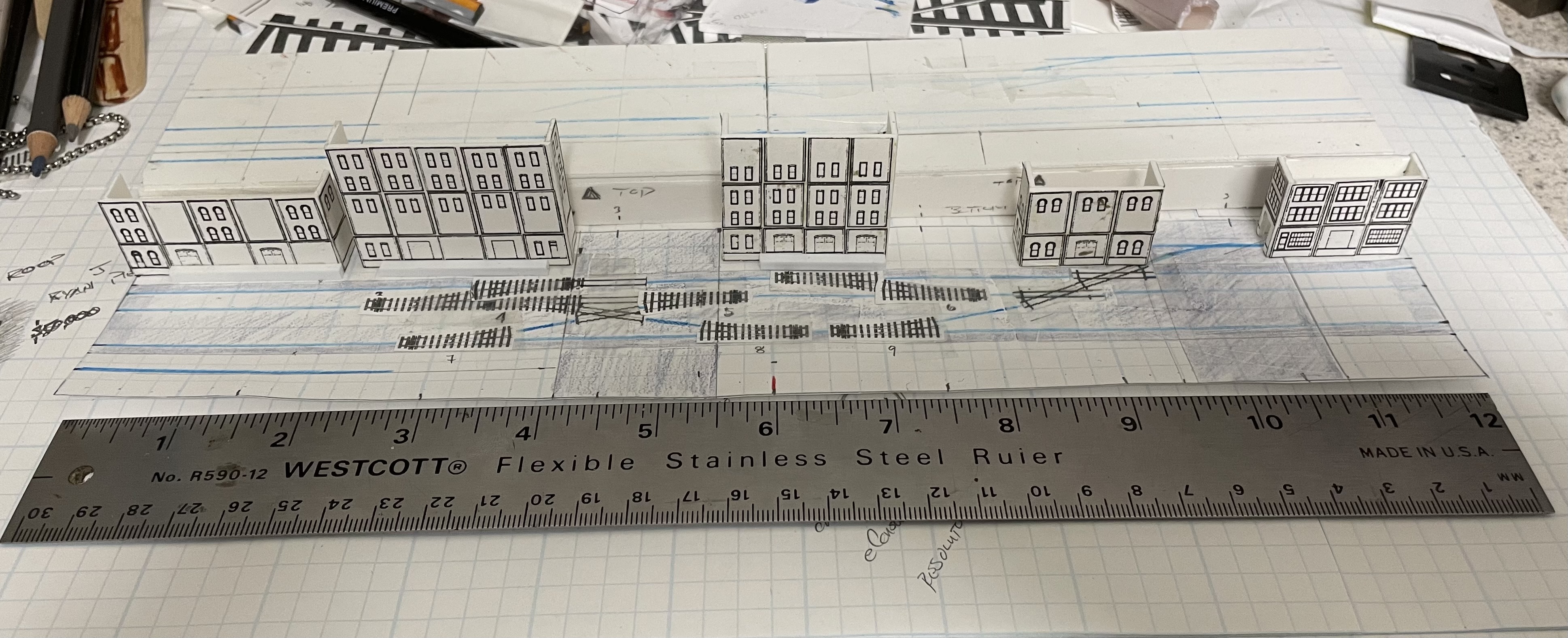
Regardless of whether I build the benchwork out of wood, foam core or blue foam the basic skeleton is going to be the same. Using a designed developed by Keiran Ryan I cut out a template for the "ribs" (trying to follow the actual process in miniature) and used that template to trace out the rest of the ribs. I made a scale 4'x8' sheet to layout everything on. 

After tracing and drawing the various components out I cut them out and this is where the trouble started. In our full sized world I can set the proper dimension on the table saw and everything would be exactly the same. I'm not that good with a knife apparently and while all the pieces, basically, looked the same they were not exactly alike. It became quite evident that my cutting skills are sub par and that there were enough differences between each rib to make building the benchwork, as intended, very difficult and in the end not good enough to continue with.

But I learned somethings in the process that I can use for the next try! Which, by the way, will substitute my small table saw for a knife. I just won't try to make a precise 4x8 cutting pattern as the kerf on the saw is way to big to pull that off.

Your basic 4'x8' piece of plywood or blue foam. I'm not sure what the biggest size of foam core would be,

This was the first layout. It wastes to much material. Need to remember to deal with the kerf which means that cutting and 8' length in half yields two pieces; one piece at 48" and one piece at 47 7/8". That means I really need the stringers to layout across the 4' short side rather than the 8' long side. Conversely I could choose to cut the 8' length exactly in half and end up with a couple of pieces that are just shy of 4' and then hope that won't mess anything up to much when I assemble the whole thing.

After a bit of trail and error I ended up with this.
Assembly begins. I'm already having issues getting it to lay flat.

And its not getting any better

And the bits after I cut it up. Some of this is probably still big enough for other things. There are still a fair number of buildings to work on after all.


Tuesday, August 20, 2024

Modeling a Model Railroad - Some Revisions

Rarely does anything survive the first pass without some tweaks and that has certainly been true for Warehouse Row. My original concept of drawing right on the model didn't work out as well as I had hoped it would. The foamed PVC sheet is soft enough that it scribes really easy making it difficult to make changes. I'm back to drawing the track plan on graph paper, which is just much easier to deal with.

I have also gone back and reconsidered what this benchwork will actually need to look like. I decided that I needed something that was going to look a bit more finished, more display like. While exploring the MRH forums about foam benchwork I came across a design recommend by Prof Klyzlr, created by Keiran Ryan, that would create a much more finished look.  I'm leaning towards using foam core as the benchwork but I'm toying with the idea of using blue or pink insulation foam as well. The local HD stocks 1/2"x4'x8' sheets and the price is attractive. I will probably still use at least 1/2" plywood where the two sections need to come together. 

Here is the revised plan along with some options on the location of the viaduct:

Revised plan, simplified

With the viaduct on the right

The issue with the viaduct on the right is switching the industry on the right side.

With the viaduct on the left

The issue with the viaduct on the left is it covers some complicated trackwork.

Visually I think the viaduct works better on the right than the left. If its on the left I think it splits the layout up to much.


Tuesday, August 13, 2024

Modeling a Model Railroad - To Complex?

I know that one of the potential issues when working on a track plan is will what you draw actually fit. I more faith for this design since I'm modifying an existing design that has been built; the Ness Street Yard by Jack "Shortliner" Trollope. There is also a shorter version of this titled Attleboro which is 6' long.

On the left side is an area of somewhat complex trackwork and while it looked like it would work just fine on my drawing I thought it would a good idea to see if it would work "full size". From the Peco website I downloaded the templates for their code 100 medium radius turnouts and 45 degree crossings. I wanted to use code 83 but there doesn't seem to be a 45 degree crossing in that line.

A little time with the printer and I put together the area in question, well minus actual straight sections but I'm not concerned with that. I laid it out "exactly" as pictured in the original plan while my drawing shows it spread out a bit more. As laid out with the templates a 50' car will not clear the two turnouts on back so I think increasing the length between turnout #1 and #2 is a good idea. The issue is that now its crossing 4' mark for the module. My initial thought is to make one module 5' long and the other 3'. This would make storage a bit of an issue but its solvable.

The other changes I made was to add turnouts #7 and #8. I'm not convinced this will add a lot of operation or not. I also added another crossing on the right side which will is necessary as I extended the back track to run the full length of the layout. I think that last siding will run into a building or perhaps a bit of vacant lot for a team track. The other possibility I'm considering is to add a turnout between #7 and #8 and run a siding to the right, front edge. That turnout could also go on the left end of #7 instead. 

Those kind of questions are what convinced me to make a "scale" model before I actually started cutting real wood or foam.

This is the plan so far. It shows where I extended the distance between turnouts 1 and 2. Where I added turnouts and crossings and where one additional turnout could be added.

A look with a few of the buildings in place. there is nothing set in stone with the buildings at this point. These are to just get an idea of what things could look like. Its missing the viaduct. I was originally thinking the viaduct should go on the left but I'm leaning towards the right side now because of the complexity of the trackage on the left.

Throwing on a few of the freight cars and the CF7 just to give a better idea of the buildings will interact with the trains.


This is the section in question, basically turnouts 1, 2, 3, 4, 5 and 6. Note this is laid out as shown in the original design. This mimics the track plan as designed as opposed to the drawn version with the extra length between turnouts 1 and 2.

Throwing a mix of 40' and 50' cars along with a CF7 for the actual sanity check. As designed anything 50' or longer will foul the switchpoints between turnouts 1 and 2.

Same scene but with an SW1200 doing the "work".