Quotes

Life is short, break the rules. Forgive quickly, kiss slowly. Love truly, laugh uncontrollably and never regret anything that makes you smile. - Samuel Longhorne Clemens (Mark Twain)
Showing posts with label Modelling a Model Railroad. Show all posts

Thursday, August 22, 2024

Modeling a Model Railroad - First Failure with the model

One of the things about this project that has kept me going is the ability to change what I'm working on as the mood strikes. While I let the latest track revisions percolate a bit I turned back to the benchwork.

Regardless of whether I build the benchwork out of wood, foam core or blue foam the basic skeleton is going to be the same. Using a designed developed by Keiran Ryan I cut out a template for the "ribs" (trying to follow the actual process in miniature) and used that template to trace out the rest of the ribs. I made a scale 4'x8' sheet to layout everything on. 

After tracing and drawing the various components out I cut them out and this is where the trouble started. In our full sized world I can set the proper dimension on the table saw and everything would be exactly the same. I'm not that good with a knife apparently and while all the pieces, basically, looked the same they were not exactly alike. It became quite evident that my cutting skills are sub par and that there were enough differences between each rib to make building the benchwork, as intended, very difficult and in the end not good enough to continue with.

But I learned somethings in the process that I can use for the next try! Which, by the way, will substitute my small table saw for a knife. I just won't try to make a precise 4x8 cutting pattern as the kerf on the saw is way to big to pull that off.

Your basic 4'x8' piece of plywood or blue foam. I'm not sure what the biggest size of foam core would be,

This was the first layout. It wastes to much material. Need to remember to deal with the kerf which means that cutting and 8' length in half yields two pieces; one piece at 48" and one piece at 47 7/8". That means I really need the stringers to layout across the 4' short side rather than the 8' long side. Conversely I could choose to cut the 8' length exactly in half and end up with a couple of pieces that are just shy of 4' and then hope that won't mess anything up to much when I assemble the whole thing.

After a bit of trail and error I ended up with this.
Assembly begins. I'm already having issues getting it to lay flat.

And its not getting any better

And the bits after I cut it up. Some of this is probably still big enough for other things. There are still a fair number of buildings to work on after all.


Tuesday, August 20, 2024

Modeling a Model Railroad - Some Revisions

Rarely does anything survive the first pass without some tweaks and that has certainly been true for Warehouse Row. My original concept of drawing right on the model didn't work out as well as I had hoped it would. The foamed PVC sheet is soft enough that it scribes really easy making it difficult to make changes. I'm back to drawing the track plan on graph paper, which is just much easier to deal with.

I have also gone back and reconsidered what this benchwork will actually need to look like. I decided that I needed something that was going to look a bit more finished, more display like. While exploring the MRH forums about foam benchwork I came across a design recommend by Prof Klyzlr, created by Keiran Ryan, that would create a much more finished look.  I'm leaning towards using foam core as the benchwork but I'm toying with the idea of using blue or pink insulation foam as well. The local HD stocks 1/2"x4'x8' sheets and the price is attractive. I will probably still use at least 1/2" plywood where the two sections need to come together. 

Here is the revised plan along with some options on the location of the viaduct:

Revised plan, simplified

With the viaduct on the right

The issue with the viaduct on the right is switching the industry on the right side.

With the viaduct on the left

The issue with the viaduct on the left is it covers some complicated trackwork.

Visually I think the viaduct works better on the right than the left. If its on the left I think it splits the layout up to much.


Tuesday, August 13, 2024

Modeling a Model Railroad - To Complex?

I know that one of the potential issues when working on a track plan is will what you draw actually fit. I more faith for this design since I'm modifying an existing design that has been built; the Ness Street Yard by Jack "Shortliner" Trollope. There is also a shorter version of this titled Attleboro which is 6' long.

On the left side is an area of somewhat complex trackwork and while it looked like it would work just fine on my drawing I thought it would a good idea to see if it would work "full size". From the Peco website I downloaded the templates for their code 100 medium radius turnouts and 45 degree crossings. I wanted to use code 83 but there doesn't seem to be a 45 degree crossing in that line.

A little time with the printer and I put together the area in question, well minus actual straight sections but I'm not concerned with that. I laid it out "exactly" as pictured in the original plan while my drawing shows it spread out a bit more. As laid out with the templates a 50' car will not clear the two turnouts on back so I think increasing the length between turnout #1 and #2 is a good idea. The issue is that now its crossing 4' mark for the module. My initial thought is to make one module 5' long and the other 3'. This would make storage a bit of an issue but its solvable.

The other changes I made was to add turnouts #7 and #8. I'm not convinced this will add a lot of operation or not. I also added another crossing on the right side which will is necessary as I extended the back track to run the full length of the layout. I think that last siding will run into a building or perhaps a bit of vacant lot for a team track. The other possibility I'm considering is to add a turnout between #7 and #8 and run a siding to the right, front edge. That turnout could also go on the left end of #7 instead. 

Those kind of questions are what convinced me to make a "scale" model before I actually started cutting real wood or foam.

This is the plan so far. It shows where I extended the distance between turnouts 1 and 2. Where I added turnouts and crossings and where one additional turnout could be added.

A look with a few of the buildings in place. there is nothing set in stone with the buildings at this point. These are to just get an idea of what things could look like. Its missing the viaduct. I was originally thinking the viaduct should go on the left but I'm leaning towards the right side now because of the complexity of the trackage on the left.

Throwing on a few of the freight cars and the CF7 just to give a better idea of the buildings will interact with the trains.


This is the section in question, basically turnouts 1, 2, 3, 4, 5 and 6. Note this is laid out as shown in the original design. This mimics the track plan as designed as opposed to the drawn version with the extra length between turnouts 1 and 2.

Throwing a mix of 40' and 50' cars along with a CF7 for the actual sanity check. As designed anything 50' or longer will foul the switchpoints between turnouts 1 and 2.

Same scene but with an SW1200 doing the "work".


Thursday, August 8, 2024

Modeling a Model Railroad - Moving Along

I have been messing around with the track plan a bit and things got kind of messy on that original plan. I laid out things a bit neater on a new piece of graph paper and I think I'm about ready to show it off in some of the railroad forums.

Along with the adjustments to the plan I have been building up some nice warehousey looking buildings to work with. There seems to be more space to fill than I anticipated. By keeping the street a scale width it keep the tracks contained and very straight, which makes it feel like I have a lot more space to fill up. 

This is where things are at, for the moment:

Working from the left to the right. Not gluing anything down at this point, everything is in flux. I really like the idea of a viaduct but it may be to much visually in such a small space.

A lower view, which doesn't look to bad.

Here it is with the updated track plan underneath. Still shifting buildings back and forth and I'm going to need to make some buildings.


Monday, August 5, 2024

Modeling a Model Railroad - A step to far?

While I was working on the track plan and the buildings I figured it would be a reasonable idea to add some freight cars and locomotives to the project. In hand I own a Rock Island SW9/1200 and 2 Santa Fe CF7s. In the near future they will be joined by 2 DRGW RS3s so I need to represent one of each of those three plus an assortment of 40' and 50' boxcars/reefers.

I initially hemmed and hawed about doing this but in the end since I was going to build the model an extra bit of visualization wasn't going to hurt and I might be able to see problems that I hadn't anticipated pushing these little blocks around.

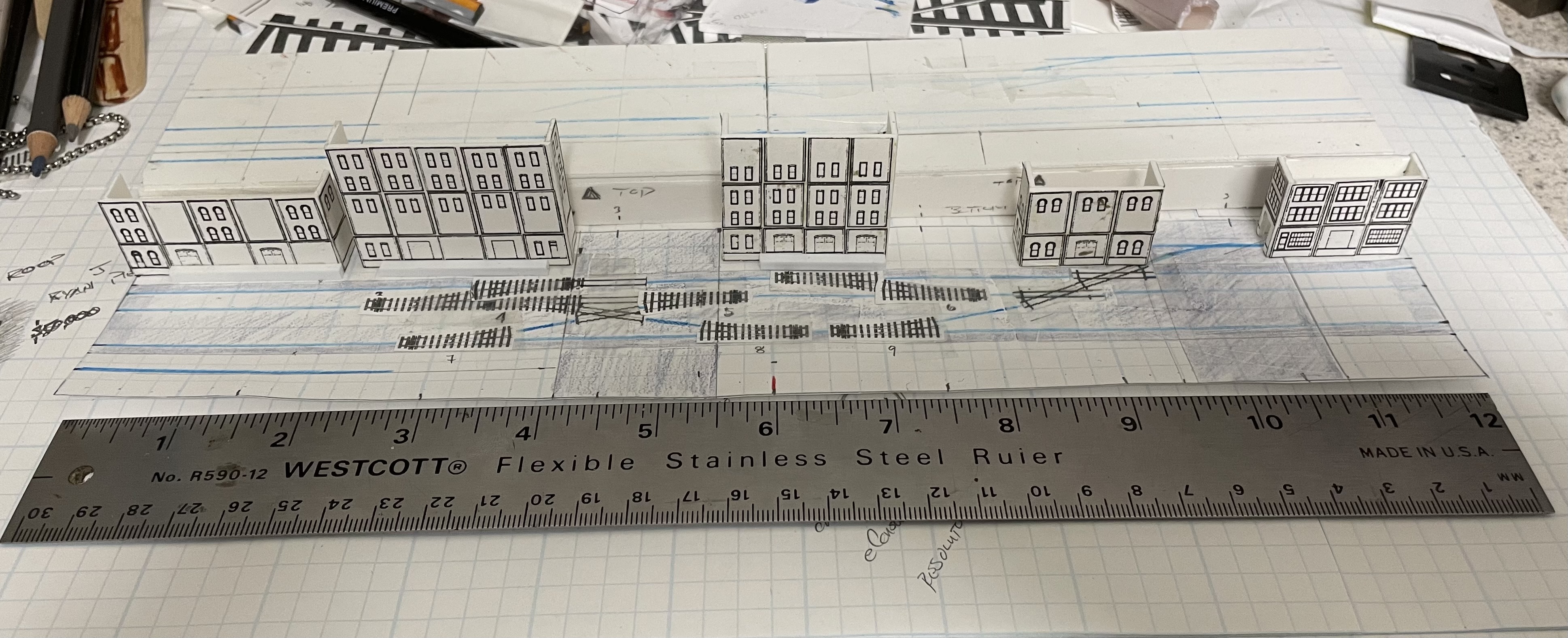
So I took some measurements and built a bunch of blocks to represent the freight cars and engines out of styrene. I was going to leave them white and then decided that was just to plain and a little color was going really help me see things better (basically the whole thing is just white with a few black and blue lines).

Since I was painting anyway I went ahead and tried to a little bit of flair to everything trying not to go to overboard on the whole thing. Which means I did resist cutting down the locomotive hoods, at least right now.

I was to busy painting to take in progress pictures so here is the finished bunch (still on the sticks).

Row 1: Rock Island SW9/1200, Santa Fe CF7, DRGW RS3
Row 2: 3 40' Generic Boxcars and 3 50' Generic Boxcars
Row 3: 3 40' DRGW Boxcars, 3 50' Generic Boxcars
Row 4: 1 40' DRGW Boxcar, 3 50' DRGW Boxcars and 1 50' Generic Boxcar
Row 5: 7 40' Generic Boxcars
3 Locomotives and 24 Boxcars. From an operational standpoint the 50' boxcars won't get used very often, 40' is going to be the common size. Figure the time period as late 1950s early 1960s.


Friday, August 2, 2024

Modeling a Model Railroad - Introducing Warehouse Row

As was mentioned in "What's Going On - 5" I'm working on a couple of planning models for two model railroads that I'm considering. At the moment I'm moving forward with the switching layout. I'm viewing this as a testbed for the eventual Wynkoop Street layout and I'm calling it Warehouse Row (although the resemblance will be pretty superficial).

Within an area of 18"x8' (Wynkoop Street will be almost 14' long) I want to represent a street running switching area. I want to include a vehicle overpass (like the 16th Street Viaduct) as well as a street level crossing (like 15th Street and Wynkoop before the overpass was built). Fairly tall buildings in the back (at least three stories and going up to 5). Buildings on the opposite will just be represented by loading docks, at least that's the thought at the moment.

I showed off building the frame for this in the WGO -5 posting. I haven't taken nearly enough pictures but at this point. The frame has been completed with a top and holes drilled in the connecting ends and are currently held together with toothpicks. Being able to split it into two pieces for storage is pretty critical for this layout since it can't remain setup indefinitely. The track plan is based on Jack Trollope's Ness Street Yard modified to represent the in the street running that I envision. Since I want the street running aspect the width of the streets is really important. According to the Sanborn Insurance maps of Wynkoop street its 80' between buildings and the road width itself is 60'. There are three streets; "main" street runs the length of the layout and the rails must fit in that 60' width (at least for the most part), the viaduct will fit in that 80' between the buildings (crossing at 90 degrees to the main street), the crossing street will keep the 80' between buildings with the street taking up 60' of that (leaving 10' on each side for sidewalk and street parking).

I'm toying with building the benchwork for this one out of foam core. There are some fascinating discussions in the MRH forum about it. While the main proponent says any foam core will work he does use a fairly high end foam core by 3M called FoamCor. Jury is out on this right now on that and its not like I'm in a hurry to get to that point.

Here are some in progress shots:


Gluing the top of the benchwork on to the frame

A copy of the Ness Street Yard has been blown up to fit (scale is 1/8 = 1").

Marking up for changes and getting a feel for how much room I have to work with.

Starting to layout out centerlines, the blue pencil marks

Going to need a few buildings. A took a copy of the Woodland Scenics templates for their modular walls and adjusted the scale to match  the 1.5 inch equals 12". My fingers got really tired clipping all of these out.

The first building; foamed PVC sheet and the photocopies.