I know that one of the potential issues when working on a track plan is will what you draw actually fit. I more faith for this design since I'm modifying an existing design that has been built; the Ness Street Yard by Jack "Shortliner" Trollope. There is also a shorter version of this titled Attleboro which is 6' long.
On the left side is an area of somewhat complex trackwork and while it looked like it would work just fine on my drawing I thought it would a good idea to see if it would work "full size". From the Peco website I downloaded the templates for their code 100 medium radius turnouts and 45 degree crossings. I wanted to use code 83 but there doesn't seem to be a 45 degree crossing in that line.
A little time with the printer and I put together the area in question, well minus actual straight sections but I'm not concerned with that. I laid it out "exactly" as pictured in the original plan while my drawing shows it spread out a bit more. As laid out with the templates a 50' car will not clear the two turnouts on back so I think increasing the length between turnout #1 and #2 is a good idea. The issue is that now its crossing 4' mark for the module. My initial thought is to make one module 5' long and the other 3'. This would make storage a bit of an issue but its solvable.
The other changes I made was to add turnouts #7 and #8. I'm not convinced this will add a lot of operation or not. I also added another crossing on the right side which will is necessary as I extended the back track to run the full length of the layout. I think that last siding will run into a building or perhaps a bit of vacant lot for a team track. The other possibility I'm considering is to add a turnout between #7 and #8 and run a siding to the right, front edge. That turnout could also go on the left end of #7 instead.
Those kind of questions are what convinced me to make a "scale" model before I actually started cutting real wood or foam.
 |
| This is the plan so far. It shows where I extended the distance between turnouts 1 and 2. Where I added turnouts and crossings and where one additional turnout could be added. |
 |
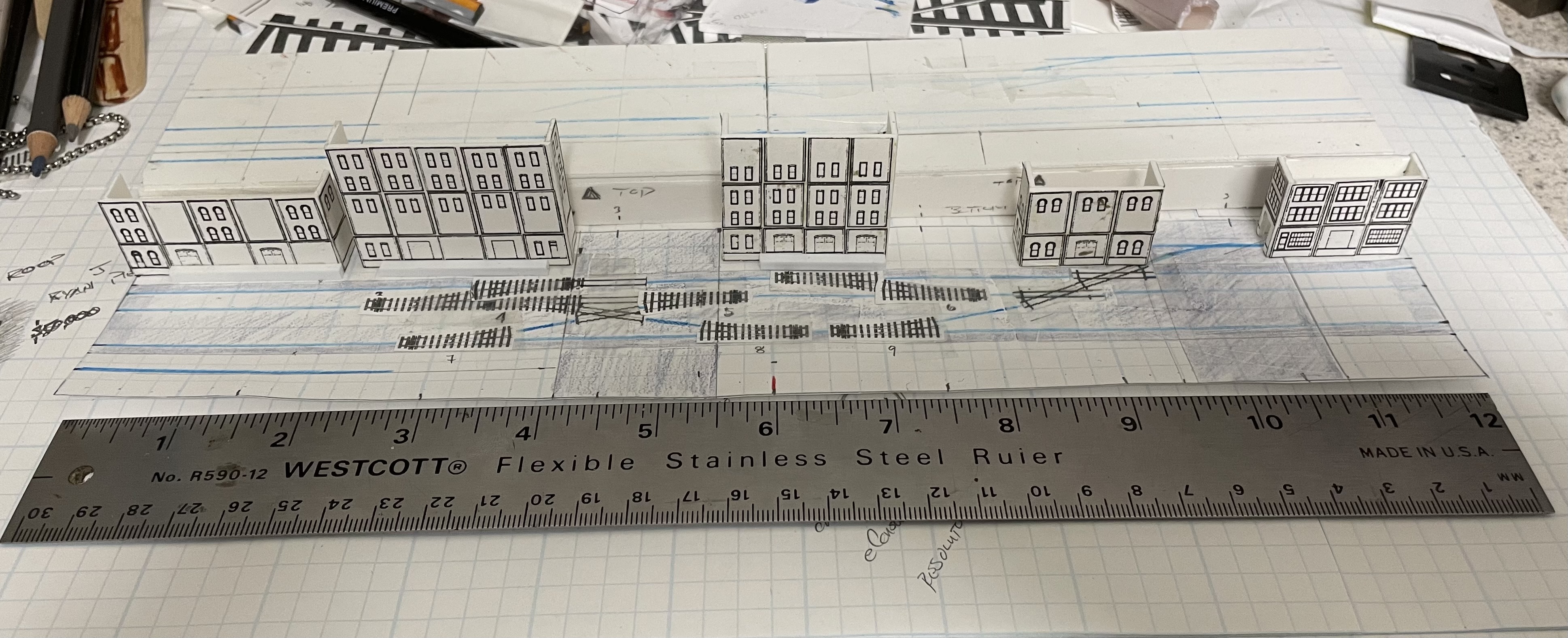
| A look with a few of the buildings in place. there is nothing set in stone with the buildings at this point. These are to just get an idea of what things could look like. Its missing the viaduct. I was originally thinking the viaduct should go on the left but I'm leaning towards the right side now because of the complexity of the trackage on the left. |
 |
| Throwing on a few of the freight cars and the CF7 just to give a better idea of the buildings will interact with the trains. |
 |
| This is the section in question, basically turnouts 1, 2, 3, 4, 5 and 6. Note this is laid out as shown in the original design. This mimics the track plan as designed as opposed to the drawn version with the extra length between turnouts 1 and 2. |
 |
| Throwing a mix of 40' and 50' cars along with a CF7 for the actual sanity check. As designed anything 50' or longer will foul the switchpoints between turnouts 1 and 2. |
 |
| Same scene but with an SW1200 doing the "work". |


No comments:
Post a Comment