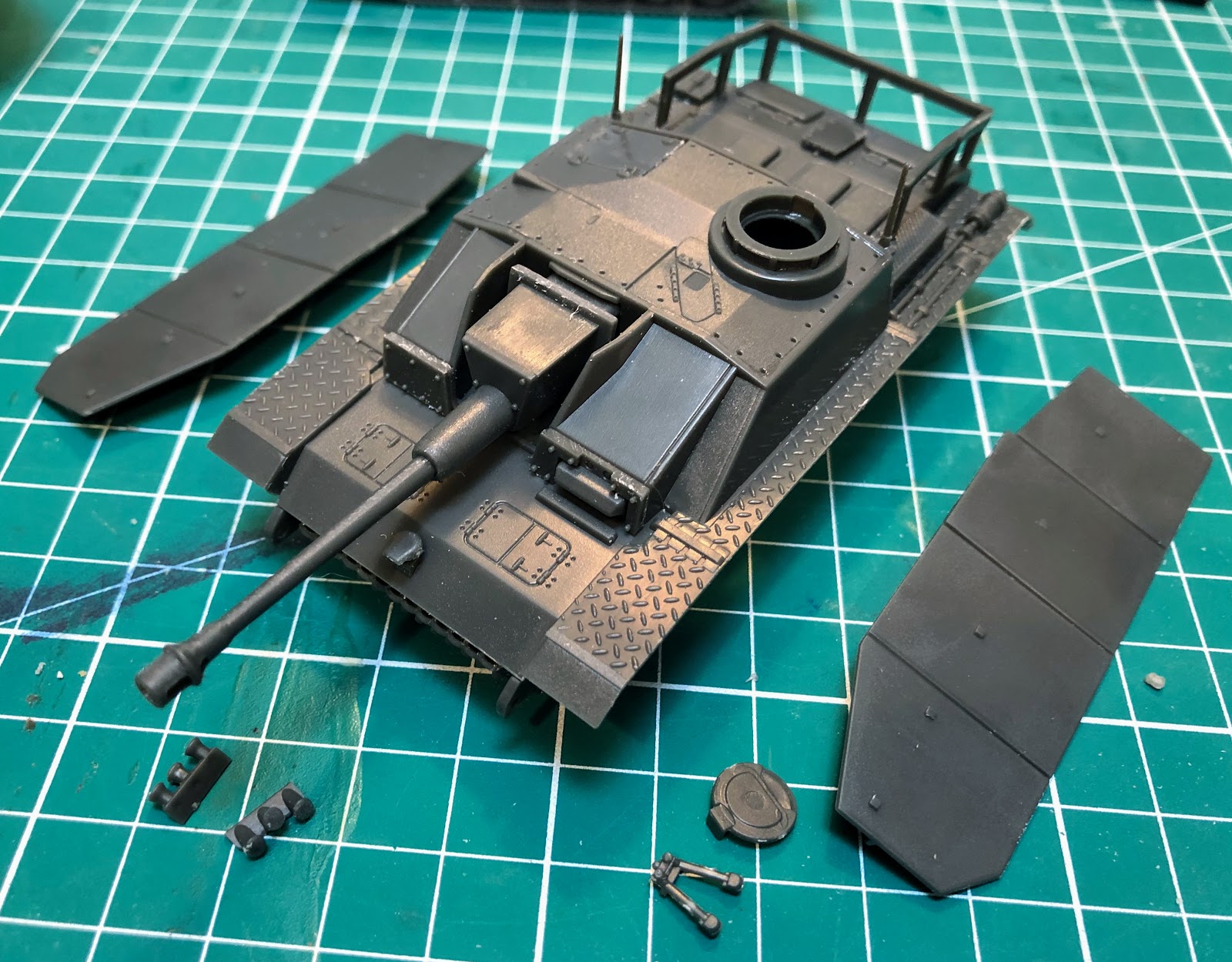
Finally managed to get over to the airbrush booth and applied some spot primer to the STuGs. I basically primed the debris shields and the backs of the skirts where I had bent the top edge. I also reprimed the lower hulls with black, hopefully to help keep those areas a bit darker. I used my favorite grey and black Stynylrez Primers from Badger for this work.
The Town of Calamity, The D&RGW RR Warehouse Row and Historical Miniature Gaming
Quotes
Thursday, November 12, 2020
Monday, November 9, 2020
World War II Project - STuG Mods - Debris Shield Finished
![]() |
| Long pieces of styrene rod in place, these get trimmed down after the glue has set |
![]() |
| After trimming |
![]() |
| Three STuGs and one STuH after mods |
![]() |
| Ready for the airbrush booth...finally |
Thursday, October 29, 2020
World War II Project - Back to the Stug - Debris Shield II
Progress has been made. I filed down the plastic that I used for the first debris shield and it looks much better although I think it sits a little to high, but I'm actually not going to worry about it. Since its a field modification there is definitely going to be some distinct difference between one vehicle and the next. I also added some strip styrene in the gap to add some strength and serve as the beginning of the weld seam. I wanted to add some rod styrene but what I had was to big and I resorted to using the .010 x .020 strip.
| Unfortunately it just seems to be really hard to capture what the edge looks like now. |
After going through this and snapping off at least three "legs" trying to recreate it. I decided that I needed a different approach. Instead of using the .030 (which is to thick visually anyway) I decided to use two pieces of .010. This way I could cut through the top piece (carefully) and the bottom piece would still hold everything together. This .010 sheet is very flexible and it worked like a charm to build the other three debris shields.
I was finally to the easy part. I glued the three shields in place, dropped in the strip styrene to fill the gap and started trimming it to fit. Once it has dried solidly I'll apply some liquid cement to the "weld" and as the plastic softens from the glue work it with a knife to resemble a weld. After that I'll add a couple of bolt heads to each side and the STuGs will finally be ready for paint...again.
| Glue them in place |
| Fill the gap |
| Starting to trim. The high part of the strip will get trimmed up after it has dried solidly. Thank goodness for sharp clippers. |
Friday, October 23, 2020
World War II Project - Back to the Stug - Debris Shield
Now that I have my spinner rack project out of the way I have had time to ruminate on how to deal with the debris shield on the STuG III. I kept trying to make this from three pieces and I now think that was a mistake. I went back to how I handled bending the top edge of the side skirts and thought that approach might work better. Well it actually worked, mostly. As you can see in the photo I have managed to get something that at least resembles the debris shield from the pictures and I might just call that good enough.
I only have three reference photos to work with. The first is from the Tank Craft book STUG III & IV, German Army, Waffen SS and Luftwaffe Western Front 1944 - 1945 (by Dennis Oliver) page 17 the second color plate has a photo reference. This is one of the better shots, although it is slightly different in appearance than the other photos. There are three photos of the same STuG in: Sturmgeschutz III on the Battlefield 2, vol 4 from Peko Publishing (by Matyas Panczel). These photos are full pagers, found on pages 99, 100 and 101. Of these the one on page 99 is the best and it is obviously at least slightly different from the one in the Tank Craft book. Its also a better photo in general. The picture on page 100 is not useful at all, but the one on page 101 you can sort of see the shield just over the top of the superstructure. Both of the STuGs in these pictures are from the 341st Sturmgeschutz-Brigade, 2nd and 3rd companies so it was definitely something peculiar to the unit along with the inward bend of the side skirts.
The thing that I'm puzzling over is how the shield was made. Did they just bend a piece of side skirt (it looks to thin to be side skirt material) or was it three pieces welded together and then bolted to something. I haven't been able to find anything that might help me on that score. However, if I continue with this method then I think I need to make it look like three pieces welded together. Without being able to find anything to contradict me, I think its the best way to proceed and finally get to the painting step on these STuGs.
![]() |
| I'm slightly concerned with the shield being to thick. It doesn't look that thick in the pictures. Its really just there to keep falling debris out of the gun mantlet. |
Monday, September 28, 2020
World War II Project - StuG III Skirt Modifications - Rubicon
| Rubicon Models STuG III ready for paint |
I started the STuG III project much earlier in the year and they have been languishing on the back of the workbench for some time now. As the U304 (f)s near completion I have pulled these out to figure out exactly what I wanted to do with them. Work has been held up for a couple of different reasons, I wanted to practice the weathering techniques that I have been using on the 21st Panzer Division vehicles and I wasn't quite sure which unit I wanted to model.
At this point I'm pretty confident with the weathering techniques and while there is always more to learn I feel that I can really do justice to the STuGs at this point. I was still undecided about the unit though, I have been flipping through a couple of books but in one of them there is a picture of a single STuG from the 343rd Battery. It has the heavy green and brown camo characteristic of the late war, and it has somewhat unusual side skirts which intrigued me. The picture indicated that these style skirts were unique to this particular unit (always a bonus in my mind). These are the standard skirts with the top of the skirting on the first three panels bent inwards. No idea why someone would do this, I don't see any gain to protection. From an armor perspective those skirts are quite thin from a metal working perspective that would take some serious effort by the maintenance unit. These STuGs also have a debris shield over the gun mantlet which would be easy to model as well (I hope anyway).
The question becomes can I modify the Rubicon skirts to reflect this interesting skirt modification? I figured I could sacrifice three panels without a problem, missing panels wouldn't be uncommon or one STuG (well probably the STuH) could go without skirts.
![]() |
| The first mark, time to get cutting |
Pushing everything else to the back of the desk I proceeded to start cutting up the side skirts. The toughest one is the front panel. In addition to the bend in the armor it has been cut down to reveal the entire drive wheel, I guessing for maintenance reasons. Determining the point of the cut was a little difficult since I had already cut the skirts panels apart from each other (perhaps I should have waited till after the painting was finished to do this, will remember that when I get to the PzKfw IVs). I lined everything up starting with the back skirt and its location relative to the return wheel and then sort of pushed everything in place till I got to the front panel and marked the positioning. The cut was made from the mark on the bottom of the panel to the upper right corner. So far so good, a small quick vertical cut to match the picture and the easy part was done.
![]() |
| Everything marked, cut and bent |
I flipped the panel over and measured on 1/8th inch down from the top of the shield, well two marks one on the front edge and one on the back edge, and proceeded to make a shallow cut here. I worked slowly since I didn't want to cut the panel and reattach it I just wanted to bend it. I made shallow cuts and then widen it on the bottom edge with a angled cut. I placed the top edge on the workbench and gently pushed, if it didn't bend I made another shallow cut, until it bent into the position I wanted. I did the same thing on the center skirts, which were much easier. The bend in the front shield required another vertical cut so it would line up straight with the next panel.
![]() |
| From the front, the important side and it looks pretty good. |
With that accomplished and the skirt panels lined back up for a quick visual check I was pleased enough with the result to do it on the rest of the skirting. I do wish I had found this picture before I had primed and based coated the STuGs! Live and learn, at least with the Jagdpanthers I already know which unit I want to represent and I planned the modifications in advance.
![]() |
| Looks good from here and the panels are behaving the way I envisioned them, kind of loose and out of place. |
![]() |
| The real work begins. |
Thursday, April 9, 2020
WWII Project - Return to the Stugs - Priming Grey
These time you get to the see the tracks and all the skirt pieces.
| I tried to keep the grey off the suspension and lower hulls. Blending just a bit on the front and back ends. |
| Lots of little skirt pieces. I cut the skirts up into their individual sections. Priming them was a pain since I didn't fasten them to anything. I know better, put did it anyway. |
Tuesday, April 7, 2020
WWII Project - Return to the Stugs - Priming
| Black on the lower hulls. I forgot to take a picture of the tracks and wheels. |
Monday, February 3, 2020
World War II Project - A trio of Stugs + 1 - next steps
After looking through a fair number of photographs it seems like StuGs didn't typically shed their side skirts to often although they did tend to come out of alignment. The unaligned look is what I'll be going for on these, with maybe one or two missing panels. I just didn't find a lot of damage to the skirts unless the vehicle had been hit and destroyed, otherwise leave them pretty much intact.
| A large pile of side skirt panels |
I'm at the point where I just need to install the tow cables and then I can start painting.
Monday, January 27, 2020
World War II Project - A trio of Stugs + 1
I decided that I would photograph the build this time in sequence with the assembly steps and try and give a few pointers. So here we go.
First up is today's work space:
Step 1 Lower Hull:
I didn't really experience any problems in this area. Everything fits together quite nicely.
Tip: when you are attaching the side plates with the running gear. Make sure you apply gently pressure downwards so that the sides don't ride up. If they ride up the back plate (B8) will not fit properly. If that piece doesn't fit properly then the upper hull won't fit well either.
| All the parts you need to build the lower hull and tracks. |
| And all put together. For these builds I will leave the tracks off for some extra detailing and painting. I probably won't attach these till after most of the painting and weathering is finished. |
This portion of the build is also very straight forward. But there are a couple of gotcha moments, one of which took me all three builds to finally figure out the best way to do it.
Tip 1: Remember that the gun mount should not be glued or your gun won't elevate. I found that if I put piece C26 in first and pushed it so the back of the piece was pointed about 45 degrees downward it was much easier to glue piece C04 to the back of it. This should be the first part of Step 2 you do.
Tip 2: B11 was a nightmare piece for me on every build, I finally found a better way to attach it on the third build of the day. Make sure the make side of the piece is perfectly flat you need all the surface area you can get and there are no pins to glue into holes. This one just goes flat against the back of the upper hull. Look closely and you can see the spots where it should be glued. There are two injection marks on the back of this piece, this is what must be filed or sanded flat to get good contact. I put glue on the two ends and on the filter (which is in the center of this). I lined it up and then put pressure on the filter itself which seemed to be the only point where I could get good pressure on the end points. Once the glue has set a bit I could shift and place my fingers on the antenna portions and make sure they were firmly attached. A couple of actual attachment pins would make this a whole lot easier.
| The parts, note the dreaded B11 piece that contains both antennas and the air filter for the rear hull |
| And assembled |
Nothing terribly difficult here, just have to decide on the extra armor and the gun.
Tip 1: If you are going to drill out the muzzle (and it looks funny if you don't) this is the time to do it. I used a smaller bit (#63) first to get the holes started and then finished up with something closer to the shell size.
| The parts with a choice between mantlets, muzzle brakes and armor. |
| And assembled |
Important: The directions in my kits are all wrong in step 4, there is a correction on the Rubicon Website but I certainly didn't think to look there for anything like this. Three of my kits were just purchased from Rubicon Models so there are a lot of old instructions out there. Essential two of the diagrams are showing the incorrect roof. The Early Production roof should be B03 not B04 and the Mid Production roof should be B04 not B03 as stated. This kind of messed me up because I was trying to build at least one early, mid and late production version of the roof, fortunately since I ended up with four kits I was able to build all three variants.
Otherwise nothing tough about this build other than that there are no marks or pins for piece B12 which is optional. Just grab a reference from the web if you are a stickler for exact location which probably varied anyway.
| The pieces, note that this is the mid production rough, which I thought was the early production roof because of the diagram in the instructions. |
| And assembled |
There are a lot of different things you can do in this particular step. Just remember that there were probably dozens of different ways these vehicles came from the factories or were changed in the field. You can't ever by "wrong".
Tip 1: If you intend to use the rack and its extensions or even just the rack then its best to glue part B05 in place first and let it set. It has a tendency to slide while the glue dries. It does not have any locator pins or even slight indentations on the hull. The best indicator of where it should go is actually in the third little box titled Late Production. If you are going to add the extensions then its really important that this piece has set up so don't hurry. Once it is glued in place then I added the two extensions. Its easier to line up the the ends of the top crosspieces and let that guide the location of the back leg. Be patient.
| Everything you need. Almost everything here can be considered optional depending on what year you are modeling. |
| And assembled. I have left the spare road wheels off so they can be painted separately. |
Lots of misc catch up detailing in this step. Side skirts are optional, smoke launchers are optional, you just have to make a decision on the top hatch and the spotting binoculars. Look around at some reference pictures, there are a lot of ways to add these pieces.
| The pieces |
At the end of the day:
| Just about all the tools I used. Two drills so I don't have to change bits, two different clippers, set of tweezers, files and the ever faithful x-acto knife variant (Gale Force Nine I think). |