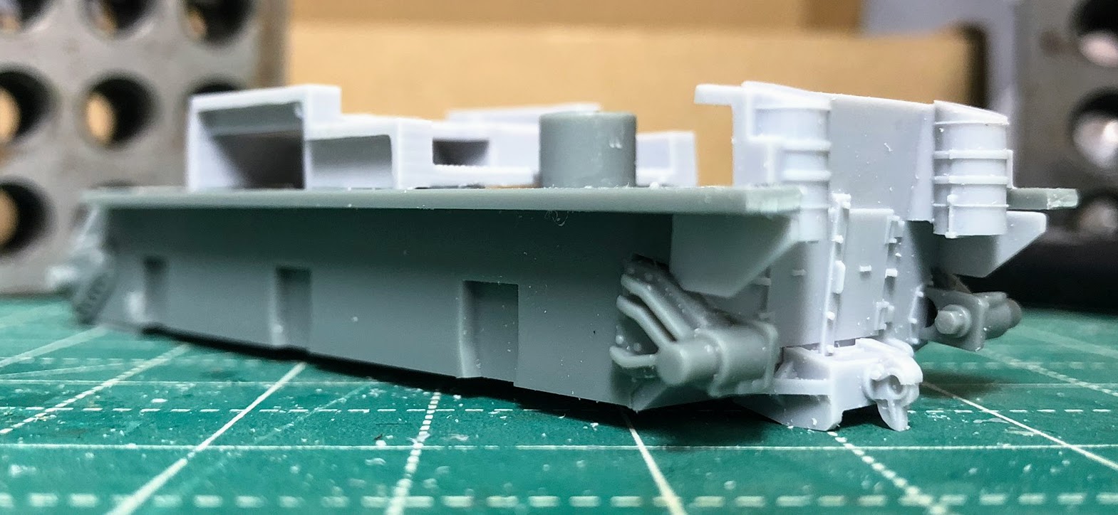
Moving on from the lower hull and "turret" brings us to the upper hull. The upper hull itself is a single piece casting, it has a bit of a warp to it but not a significant one and I think that most of the assembly will help straighten out just fine without resorting to a hot water treatment. Details are crisp and the casting itself is very clean.
Step 5 Upper Hull
Here you step right into adding details to the hull, nothing difficult at all. Other than the MG off of the plastic sprue everything in this step is resin and secured with a drop or two of super glue.
Step 6 Mortar
This is a really nice pewter casting. Probably one of the best looking and easiest to assemble mortars that I have ever worked with.
Step 7 (7A & 7B)
Here we add a bunch of pewter detail pieces as well as the mortar that was assembled in step 6. Again no surprises although piece P10 had the most significant mold lines to clean up at this point. In 7B resin detail pieces are added to the back deck. Pretty darn straight forward build at this point.
Step 8 Vehicle Assembly
Its time to bring everything together or, in my case, just dry fit everything and make sure it goes together. For painting purposes I want to keep some of the sub-assemblies separate to make them easier to paint. In my case I will assemble the upper and lower hull together while leaving off the tracks and the "turret". While the majority of the interior is going to be hidden once the turret is on I do want to get some basic painting completed inside and it will be quite a bit more difficult with the turret attached.
Here I really ran into my first issue with the kit. As I test fitted the upper and lower hull together I discovered a significant gap between the riveted front end of the upper hull and the spot where it should meet the lower hull. At this point I made sure that there wasn't anything blocking the upper hull from sliding all the way down the posts. Here I found that I needed to further trim the rear of the lower hull as I had left it a tad to long. Now the back end fitted together snugly. I also trimmed a bit more off a couple of the ribs located in the upper hull thinking that they maybe keeping things apart when bringing the two components together.
 |
Something doesn't seem quite right here.
|
 |
Pretty sure there shouldn't be a gap here.
|
 |
What is going on? Time to troubleshoot.
|
 |
Working back to front. I didn't cut off enough from the end of the lower hull. I carefully trimmed the circled section more for a snug fit.
|
 |
These two ribs may stick out a bit to much so I clipped them a little bit to make sure there was enough clearance.
|
 |
After clipping
|
Continuing my way forward I checked that the font fenders weren't interfering with anything and did file off a couple of corners that might be effecting the fit. At this point I still had the gap in the front although I had managed to narrow it quite a bit.
All of these steps closed the gap a bit, but not enough. My first thought at this point was to cut the big post out and go from there but that seemed rather extreme. I opted to take a look at the lower hull and see if I could alleviate the problem from another angle.
 |
| On the lower hull the front edge is physically to high at this point. They are above the tabs located on the resin transmission cover. I don't know if this is a fault with the kit or my construction. However its easily fixed with a file. |
 |
Much better, the two surfaces are now even with each other. A quick test fit revealed that this almost fixed the gap, but there is still a sliver visible. I can't push the upper hull down far enough to cover the gap.
|
 |
Looking back at the upper hull the post has two "wings" these keep the upper hull from going to low. In the picture the upper hull is just resting in position. Pushing it down to the point where the wings contact the lower locating post is leaving that sliver of gap that I'm seeing at this point.
|
Now that I see what is keeping the upper hull from going down to far its a simple matter of trimming the "wings" on the upper hull locator post. I tried to trim slowly but still managed to cut a tad to much off, but the gap is filled and that seems like better stop point for the upper hull. Now I'm gluing resin to plastic and there isn't anyway to hit all seven contact points with super glue and have a prayer of getting it in place fast enough before something sets. So the gluing sequence is critical at least in my mind.
1. Using gel type super glue I applied a bead to the three tabs in the front, two are on the transmission cover and the third is on the upper hull. I then pushed the upper hull down far enough to close the gap completely and cleaned up any excess super glue as quickly as I could.
2. Apply a more fluid type of super glue to the forward locating post so that it flows in between the front locator posts.
3. Pushing the rear locator post down till the "wings" contact the lower post and apply super glue (fluid? liquid?)
4. At the rear make sure that the back two edges of the lower hull are even with the edge of the upper hull and using the same "liquid" super glue apply a minute amount here to complete the gluing sequence.
 |
Apply the gel super glue in front and push hull down to fill the gap
|
 |
Apply "liquid" super glue on the front locator post and "wings"
|
 |
Push the rear hull down till the wings are touching the top of the bottom post. Apply "liquid" super glue on the back locator post and"wings"
|
 |
Apply more "liquid" super glue to the plastic and resin meeting point after making sure both sides are even with each other.
|
After all that is done you can glue P09 to the front glacis which also serves to help hold the upper and lower hulls together.
A huge shout out to Rubicon Models at this point. P09 didn't make it into my bag of pewter parts and I missed that in my quicky inventory at the beginning of all this. They had it in the mail to me that day and it only took a couple of days to arrive. Can't really express how much I appreciate them going above and beyond to get me that part.
Step 9
Seems almost superfluous at this point but resin part R018 is attached to the rear hull, that is until you try to figure out just how to attach it from the instructions. The instructions show a cross-section of the rear which is just not helpful. A couple of pictures would explain the attachment a bit better, although once you are looking from the bottom it becomes pretty obvious.
And here ends the build so far. The "turret" is finished, the upper and lower hulls are assembled together and the tracks are finished. The only things I have completely glued together are the upper and lower hull everything else is separate at this point for painting. I have also found a number of reference pictures and notations that show some weld seams on the "turret" I'm contemplating adding those before painting. The other thing I would like to do is roughen up the surface of the upper hull and transmission. Since these were all castings they shouldn't be smooth but should have some texture to them. I'm still looking at ways to accomplish this. In retrospect I should have thought about this before I did any assembly, so put this thought in the contemplation phase for the moment.
Sorry for the harsh pictures on these pictures but here is a look at how the M32B1 is looking so far.