Quotes

Life is short, break the rules. Forgive quickly, kiss slowly. Love truly, laugh uncontrollably and never regret anything that makes you smile. - Samuel Longhorne Clemens (Mark Twain)
Showing posts with label Rubicon Models Resin. Show all posts

Thursday, September 17, 2020

World War II Project - M32B1 ARV Pt 3 - Rubicon Models

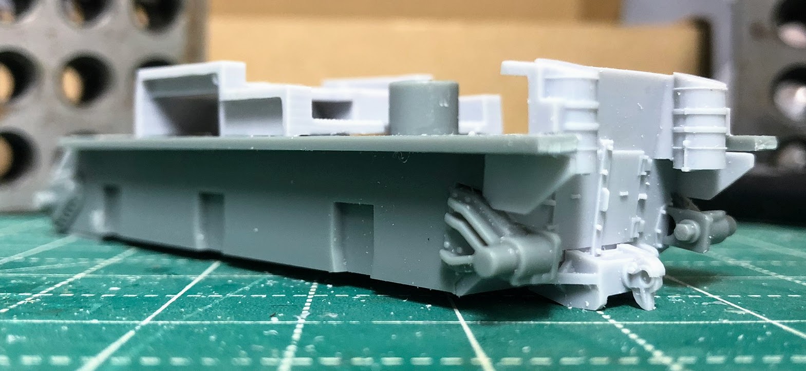
After the hull has been assembled its time to move on to the A-frame crane. This can be assembled in either the standby/travel mode or in operating mode. The decision here is forced a little early in the assembly (Step 3A) of the model, but if you have left the "turret" off you could change your mind and pry up which ever piece you used and replace it with the other (R08 or R09).  I have been committed to the operating mode from the beginning of this build as I don't really intend it to be a gaming piece (although I suppose it could become a big objective marker). I might get a second one and build it in travel mode for the wargame table.

Step 10 - The A-frame

You would think this is pretty straightforward assembly involving three components; P01, P02 and P03. The reality is different. Clean up any mold lines on these pieces while you contemplate the rest of the build. If you haven't decided on Standby/Travel or Operating Mode you must do so now which will determine how much work you need to do. Something to think about, if you don't mind rigging cables then you are good with either mode. If you don't want to fiddle around with wire or thread to represent said cables, then Standby or Travel mode is for you.

P01 The A-Frame, P02 Hook Block, P03 Limiter (for lack of a better term on my part)

For Standby/Travel Mode: Don't try and glue the pieces together and hope you will get the angles right. Glue P1 (the A-Frame) and P03 (Limiter) together first. There is only one way for them to fit together so you can't go wrong there. Attaching P02 can be tricky because its going to sit at a different angle in Standby/Travel mode than it does for Operating Mode. There are two small pins on P02 and those will fit into the holes/dimples on the attachment point on the A-frame. Push it into place, DON'T GLUE IT YET, make sure it is in position and then take a pair of pliers and gently squeeze the outside pieces of the A-frame together trapping P02 in place. Now skip to Step 11. Gently put the feet of the A-frame into place at the front. The fit is relatively tight so be careful because you are dealing with a resin attachment point. With the front feet in place set the feet of the hook block (P02) into place on the back of the ARV. Now everything should look like this:


With all of this in place you can place a drop of super glue at each attachment point including the wheel block at the A-Frame attachment point and you are ready to roll.

For Operating Mode there are a couple of things you should do before you glue these pieces together. Make sure you have found and cleaned up any mold lines remaining on these pieces. P02 the hook block needs some holes drilled in it for operating mode. Much easier to drill those now than after its been assembled in Step 13.  It is much easier to drill the three 1mm holes you need in the hook block (P02) before you try getting everything into place.

The hole at the top of the tackle block. Mine is not straight, its centered on this side but exited the other side less than centered.

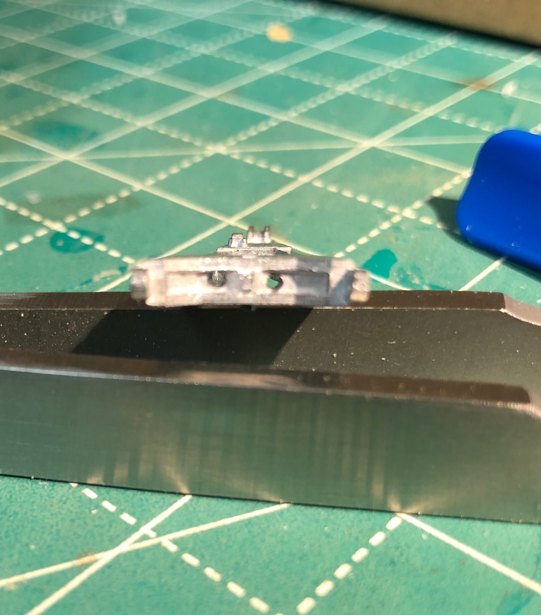
They may be straight through but they are definitely not centered. Fortunately no one will ever know (well except if you looked at the pictures, then it will be forever etched on your mind).

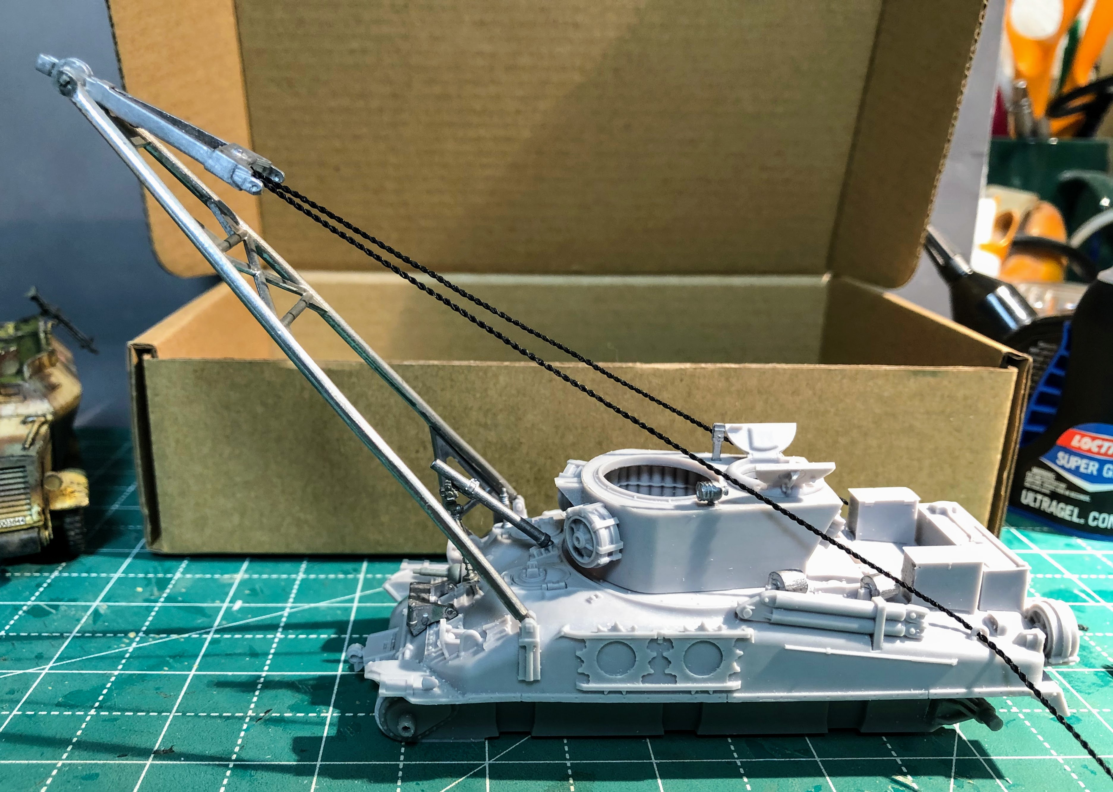
Just like for Standby/Travel mode don't try and glue the pieces together and hope you will get the angles right. Glue P1 (the A-Frame) and P03 together first. There is only one way for them to fit together so you can't go wrong there. Attaching P02 (Hook Block) can be tricky because its going to sit at a different angle in Standby/Travel mode than it does for Operating Mode. There are two small pins on P02 and those will fit into the holes/dimples on the attachment point on the A-frame. Slip it into place, DON'T GLUE IT YET, make sure it is in position and then take a pair of pliers and gently squeeze the outside pieces of the A-frame together trapping P02 in place. Now skip to Step 13 and get out whatever you are going to use for cabling.  Make sure you have drilled the other three holes needed for Operating Mode. There is one in the "turret" front and the others are the two D-hooks on the rear of the vehicle. Once you have that done you can continue forward. Gently put the feet of the A-frame into place at the front. The fit is relatively tight so be careful because you are dealing with a resin attachment point and you don't want to accidentally snap it off. With the front feet in place raise the A-frame to its full upright position, you can tell because the limiter piece will rest against the block on the right side of the hull and stop. You should be at the point pictured  below (I placed a very small drop of super glue at the top to sort of freeze the hook block into place).


Now thread your cable, start at one of the D-hooks on the rear, then through the hole on the side that matches the D-hook over to the other hole in the hook block and back down through the D-hook on the other side. Please note that your cable should not cross over itself to form an X!

The next bit I'm not sure about. It makes sense to me that that "arms" of the hook block should be pretty much in line with the cables when they are taut. I pulled the string taut, broke the super glue at the A-frame attachment point and then re-glued it when it was in the position I wanted. Then you can glue everything in place. I did remove the cable and I'll re-thread that after painting or during the detail painting so it can be properly weathered.

Cables are taut, glue has not been "broken" the angle doesn't look right to me so I "broke" the glue so I could adjust the hook block. I could have but did not glue the A-Frame into place. You certainly can, the only thing that needs to move right now is the hook block. In theory you could make the whole thing "working" but I don't feel that it would be worth the effort.

I'm much happier with this angle so I applied super glue to the A-frame/Hook Block attachment point. I didn't glue the cable into place so I could remove it for painting. [Update; while paging through my Zaloga books I found a couple of pictures that I missed. It did prove my guess that the hook block arms should be basically parallel to the cable when the crane is deployed.]


Step 11 - Standby/Travel Mode 

I'm skipping this step all together, and if you followed the directions above you are already finished with this step.

Step 12 - Operating mode

If you have followed the steps above for Step 10 you have basically completed this step.


Step 13 - Cabling

The instructions call this part optional but since its in operating mode its going to look pretty silly without the cabling in place. If you followed the instructions in step 10 for operating mode then you are ready to do all the cabling. I'll won't really complete this step until after the painting has been completed.

That wraps up the build now its time to move on to painting. I have the M4A3E2 and M4A3 and an M4A1 that will be painted (or for the M4A1 repainted) to more or less match.

References are hard to come by for the M32B1 or any of them for that matter. I have found pictures a few pictures of them in the following books (there may be others, these are just ones I have on hand).

Armored Strike Force by Charles C Roberts Jr

Armored Thunderbolt by Steven Zaloga

Armored Attack 1944 by Steven Zaloga

Armored Victory 1945 by Steven Zaloga

Allied-Axis Photo Journal Issue 4

There are also photos online mostly of completed plastic kits which might be your best reference. There are very few photos of the M32B1 in Operating Mode.

Wednesday, September 16, 2020

World War II Project - M32B1 ARV Pt 2 - Rubicon Models

Moving on from the lower hull and "turret" brings us to the upper hull. The upper hull itself is a single piece casting, it has a bit of a warp to it but not a significant one and I think that most of the assembly will help straighten out just fine without resorting to a hot water treatment. Details are crisp and the casting itself is very clean. 

Step 5 Upper Hull

Here you step right into adding details to the hull, nothing difficult at all. Other than the MG off of the plastic sprue everything in this step is resin and secured with a drop or two of super glue.

Step 6 Mortar

This is a really nice pewter casting. Probably one of the best looking and easiest to assemble mortars that I have ever worked with.

Step 7 (7A & 7B)

Here we add a bunch of pewter detail pieces as well as the mortar that was assembled in step 6. Again no surprises although piece P10 had the most significant mold lines to clean up at this point. In 7B resin detail pieces are added to the back deck. Pretty darn straight forward build at this point.


Step 8 Vehicle Assembly

Its time to bring everything together or, in my case, just dry fit everything and make sure it goes together. For painting purposes I want to keep some of the sub-assemblies separate to make them easier to paint. In my case I will assemble the upper and lower hull together while leaving off the tracks and the "turret".  While the majority of the interior is going to be hidden once the turret is on I do want to get some basic painting completed inside and it will be quite a bit more difficult with the turret attached.

Here I really ran into my first issue with the kit. As I test fitted the upper and lower hull together I discovered a significant gap between the riveted front end of the upper hull and the spot where it should meet the lower hull. At this point I made sure that there wasn't anything blocking the upper hull from sliding all the way down the posts. Here I found that I needed to further trim the rear of the lower hull as I had left it a tad to long. Now the back end fitted together snugly. I also trimmed a bit more off a couple of the ribs located in the upper hull thinking that they maybe keeping things apart when bringing the two components together.

Something doesn't seem quite right here.

Pretty sure there shouldn't be a gap here.

What is going on? Time to troubleshoot.

Working back to front. I didn't cut off enough from the end of the lower hull. I carefully trimmed the circled section more for a snug fit.

These two ribs may stick out a bit to much so I clipped them a little bit to make sure there was enough clearance.

After clipping

Continuing my way forward I checked that the font fenders weren't interfering with anything and did file off a couple of corners that might be effecting the fit. At this point I still had the gap in the front although I had managed to narrow it quite a bit.


All of these steps closed the gap a bit, but not enough. My first thought at this point was to cut the big post out and go from there but that seemed rather extreme. I opted to take a look at the lower hull and see if I could alleviate the problem from another angle.

On the lower hull the front edge is physically to high at this point. They are above the tabs located on the resin transmission cover. I don't know if this is a fault with the kit or my construction. However its easily fixed with a file.

Much better, the two surfaces are now even with each other. A quick test fit revealed that this almost fixed the gap, but there is still a sliver visible. I can't push the upper hull down far enough to cover the gap.


Looking back at the upper hull the post has two "wings" these keep the upper hull from going to low. In the picture the upper hull is just resting in position. Pushing it down to the point where the wings contact the lower locating post is leaving that sliver of gap that I'm seeing at this point.


Now that I see what is keeping the upper hull from going down to far its a simple matter of trimming the "wings" on the upper hull locator post. I tried to trim slowly but still managed to cut a tad to much off, but the gap is filled and that seems like better stop point for the upper hull. Now I'm gluing resin to plastic and there isn't anyway to hit all seven contact points with super glue and have a prayer of getting it in place fast enough before something sets. So the gluing sequence is critical at least in my mind.

    1. Using gel type super glue I applied a bead to the three tabs in the front, two are on the transmission cover and the third is on the upper hull. I then pushed the upper hull down far enough to close the gap completely and cleaned up any excess super glue as quickly as I could.

    2. Apply a more fluid type of super glue to the forward locating post so that it flows in between the front locator posts.

    3. Pushing the rear locator post down till the "wings" contact the lower post and apply super glue (fluid? liquid?)

    4. At the rear make sure that the back two edges of the lower hull are even with the edge of the upper hull and using the same "liquid" super glue apply a minute amount here to complete the gluing sequence.

Apply the gel super glue in front and push hull down to fill the gap

Apply "liquid" super glue on the front locator post and "wings"

Push the rear hull down till the wings are touching the top of the bottom post. Apply "liquid" super glue on the back locator post and"wings"

Apply more "liquid" super glue to the plastic and resin meeting point after making sure both sides are even with each other.

After all that is done you can glue P09 to the front glacis which also serves to help hold the upper and lower hulls together.

A huge shout out to Rubicon Models at this point. P09 didn't make it into my bag of pewter parts and I missed that in my quicky inventory at the beginning of all this. They had it in the mail to me that day and it only took a couple of days to arrive. Can't really express how much I appreciate them going above and beyond to get me that part.

Step 9
Seems almost superfluous at this point but resin part R018 is attached to the rear hull, that is until you try to figure out just how to attach it from the instructions. The instructions show a cross-section of the rear which is just not helpful. A couple of pictures would explain the attachment a bit better, although once you are looking from the bottom it becomes pretty obvious.


And here ends the build so far. The "turret" is finished, the upper and lower hulls are assembled together and the tracks are finished. The only things I have completely glued together are the upper and lower hull everything else is separate at this point for painting. I have also found a number of reference pictures and notations that show some weld seams on the "turret" I'm contemplating adding those before painting. The other thing I would like to do is roughen up the surface of the upper hull and transmission. Since these were all castings they shouldn't be smooth but should have some texture to them. I'm still looking at ways to accomplish this. In retrospect I should have thought about this before I did any assembly, so put this thought in the contemplation phase for the moment.

Sorry for the harsh pictures on these pictures but here is a look at how the M32B1 is looking so far.


Tuesday, September 15, 2020

World War II Project - M32B1 ARV Pt 1 - Rubicon Models

I unboxed this kit about a week ago and I have been very excited to start working on it. I still need to finish the Jumbo Sherman, but that build has stalled a little bit trying to figure out how I can fix the 76mm gun since I used the wrong one there. No reason not to get started on this one though. Its a pretty new kit and its mostly resin so I figured I would do a step by step on it and maybe help other builders solve any problems that might exist with this one.

I must say that right out of the box this is a great looking kit, clean crisp resin castings and equally clean crisp pewter castings including a beautiful .50 caliber MG.

Step 1 (1A & 1B) Tracks
Like just about every Rubicon build you start off with the tracks. This kit uses the tracks with the VVSS bogies and comes off the single plastic sprue. A single pewter part is added to the right hand track's drive sprocket. A little super glue does the trick here just be sure you have it facing the right way when you glue it on.


Step 2 (2A & 2B) Lower Hull
Moving right into the resin assembly in step 2. The back plate for the engine compartment and a tow hitch are glued together. You will need superglue for this. For this type of construction I like to use a gel type superglue its less messy and you have a tad bit more time to work. Right now I'm trying Locktite Super Glue; Ultragel. Following this glue the sides of the lower (plastic) hull together. You will need to trim a bit off the back end of the lower hull so the upper hull will fit on correctly. Plastic parts A02 and A10 should be added last or at least after you have glued on the engine compartment back plate. The resin transmission cover and front tow hitch can then be glue in place. Be sure to test fit the transmission cover and be sure you have it oriented right and that the fit is tight against the front of the lower hull. 

This is the section of the lower hull that you will need to trim. Instructions say 1.5mm which is tough to measure. Better to cut a bit to short as it will be hidden by the upper hull when assembled. Leave it to long (like I did) and its harder to trim to fit, however, you will get a tighter fit that way.


Step 3 (Step 3A & 3B)
This is the internal assembly for the winch and a good chunk of the interior of the lower hull that can be seen. Unfortunately you have quickly arrived at the point when you need to decide if you are going to have the crane in Standby (or travel) Mode or in Operating Mode. For travel mode use part R09 which features a closed cover so you can't see the cable reel. For operating mode use part R08 which is an open cover and allows access to the cable reel. If you change your mind later on I wouldn't worry about it to much, all of this is buried fairly deep inside and unless you remove the turret you probably won't be able to tell if the cover is opened or closed anyway, however, with it open you can thread your wire or thread all the way down to the reel. Make that decision and then glue the whole assembly to the lower hull, it fits between the two posts although its not a tight fit. I elected to fit mine tight against the front post and leave a small gap at the back post.

You can also glue the tracks in place at this stage. I prefer to leave them off so that I can paint them separately and assemble them after that.


Step 4 (4A, 4B & 4C)
Here begins the assembly of the "turret" probably more properly a superstructure. It does not have a turret ring it is not intended to swivel. This is a pretty straight forward bit of assembly of resin and pewter parts. The only decision will be if you want the hatch opened or closed, which determines if you will be using piece R10 (open) or R11 (closed). I went for open just so more of the interior is visible (although really it doesn't add that much, if I were to build another one I would just go for the closed hatch). I did encounter one issue here. Everything in these three steps has something to add you in where it goes, a notch, a pin or something. While Step 4A clearly shows such a small rectangular protrusion for piece P14 it is not there (at least not on the casting I received). Fortunately this piece sits dead center on the back part of the superstructure and there is a detail piece on the outside that is also in the center. Just use that to line up the placement of P14. P14 is the seat so if you went with a closed hatch you can just leave it off.

Step 4A
 
The location of P14


The beginning of Step 4B, you can see how the seat (P14) is centered underneath the opening for the hatch.

All glued up and ready for action. I didn't glue the .50 cal in place, its in a spot that could be problematic with threading cable (wire or thread) if you opt for the operating mode like I did. You are also probably better off with a closed hatch for operating mode as well.