I must say that right out of the box this is a great looking kit, clean crisp resin castings and equally clean crisp pewter castings including a beautiful .50 caliber MG.
Step 1 (1A & 1B) Tracks
Like just about every Rubicon build you start off with the tracks. This kit uses the tracks with the VVSS bogies and comes off the single plastic sprue. A single pewter part is added to the right hand track's drive sprocket. A little super glue does the trick here just be sure you have it facing the right way when you glue it on.

Moving right into the resin assembly in step 2. The back plate for the engine compartment and a tow hitch are glued together. You will need superglue for this. For this type of construction I like to use a gel type superglue its less messy and you have a tad bit more time to work. Right now I'm trying Locktite Super Glue; Ultragel. Following this glue the sides of the lower (plastic) hull together. You will need to trim a bit off the back end of the lower hull so the upper hull will fit on correctly. Plastic parts A02 and A10 should be added last or at least after you have glued on the engine compartment back plate. The resin transmission cover and front tow hitch can then be glue in place. Be sure to test fit the transmission cover and be sure you have it oriented right and that the fit is tight against the front of the lower hull.
 |
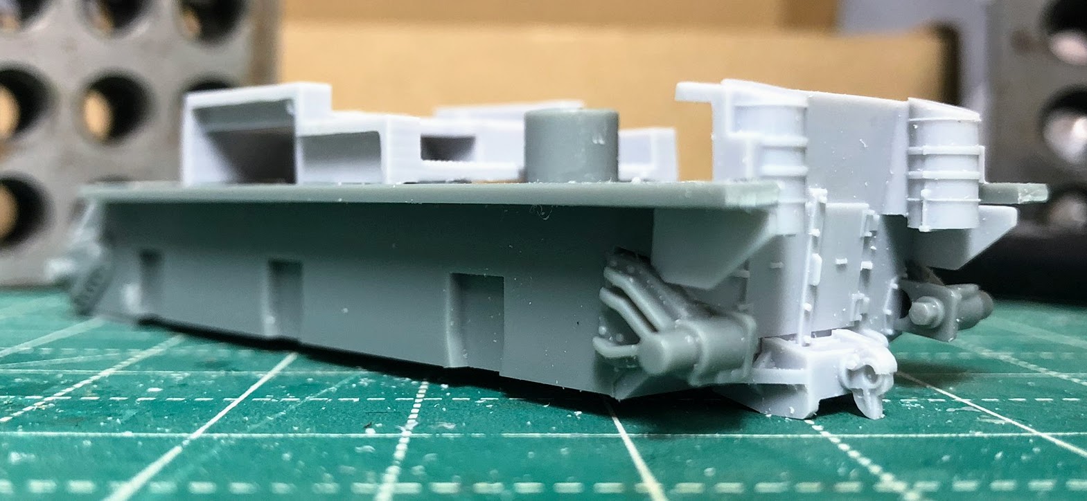
| This is the section of the lower hull that you will need to trim. Instructions say 1.5mm which is tough to measure. Better to cut a bit to short as it will be hidden by the upper hull when assembled. Leave it to long (like I did) and its harder to trim to fit, however, you will get a tighter fit that way. |

This is the internal assembly for the winch and a good chunk of the interior of the lower hull that can be seen. Unfortunately you have quickly arrived at the point when you need to decide if you are going to have the crane in Standby (or travel) Mode or in Operating Mode. For travel mode use part R09 which features a closed cover so you can't see the cable reel. For operating mode use part R08 which is an open cover and allows access to the cable reel. If you change your mind later on I wouldn't worry about it to much, all of this is buried fairly deep inside and unless you remove the turret you probably won't be able to tell if the cover is opened or closed anyway, however, with it open you can thread your wire or thread all the way down to the reel. Make that decision and then glue the whole assembly to the lower hull, it fits between the two posts although its not a tight fit. I elected to fit mine tight against the front post and leave a small gap at the back post.
You can also glue the tracks in place at this stage. I prefer to leave them off so that I can paint them separately and assemble them after that.


Step 4 (4A, 4B & 4C)
Here begins the assembly of the "turret" probably more properly a superstructure. It does not have a turret ring it is not intended to swivel. This is a pretty straight forward bit of assembly of resin and pewter parts. The only decision will be if you want the hatch opened or closed, which determines if you will be using piece R10 (open) or R11 (closed). I went for open just so more of the interior is visible (although really it doesn't add that much, if I were to build another one I would just go for the closed hatch). I did encounter one issue here. Everything in these three steps has something to add you in where it goes, a notch, a pin or something. While Step 4A clearly shows such a small rectangular protrusion for piece P14 it is not there (at least not on the casting I received). Fortunately this piece sits dead center on the back part of the superstructure and there is a detail piece on the outside that is also in the center. Just use that to line up the placement of P14. P14 is the seat so if you went with a closed hatch you can just leave it off.
 |
| Step 4A |
 |
| The location of P14 |

 |
| The beginning of Step 4B, you can see how the seat (P14) is centered underneath the opening for the hatch. |
 |
| All glued up and ready for action. I didn't glue the .50 cal in place, its in a spot that could be problematic with threading cable (wire or thread) if you opt for the operating mode like I did. You are also probably better off with a closed hatch for operating mode as well. |

Looking great so far. Mixed media kits like this are always fascinating to me. And Gel super glue seems like a must for all the "add ons".
ReplyDeleteAs for the Jumbo, since the pre-brake version of the 76mm cannon had the thread covers, you could probably cut the brake off and replace with some plastic rod of the correct diameter.
So far the M32 has been a fun build. I have had the Jumbo on my mind and I'm cutting it off right behind the muzzle brake is something I have been contemplating.
Delete